I’m considering buying a pair of Ten64 boxes, and in my application I want to install Reyax GPS receiver modules into P11. These modules communicate using power and USB2, so I expect they are functionally compatible with that slot.
However, they also expose a PPS (Pulse Per Second) signal on pin 42 of the connector, and I need to be able to connect that to a GPIO. On the Ten64 schematic pin 42 of P11 is marked as “no connect”, but is it actually connected to pad, trace, or test point? I’d like to understand if it will be possible to tack a wire onto the pin.
If P11 is an SMT connector, not through-hole, and pin 42 is literally not connected at all, that will not be compatible with my plans 
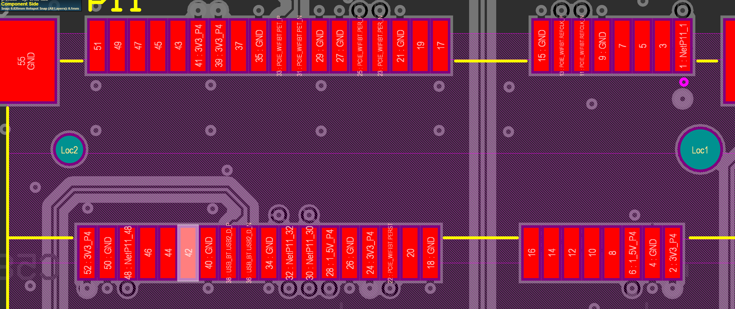
Good news - pin 42 is not connected to anything (highlighted below):
All the pins on the miniPCIe connector are soldered onto pads. It’s definitely possible to tack a wire onto a single pin.
Just be careful not to short onto the GND on 40!
Also, this side of the connector will be “under” the card when inserted.
edit: On a re-read of your last sentence, yes, the connector is SMT but has long ‘pins’ making it easier to solder wires onto individual pins.
If you’re not familiar with miniPCIe board connectors, they look like this:
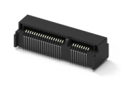
(source: https://www.attend.com.tw/product.php?act=view&id=127)
1 Like
Thanks! That will definitely work for my application. Unfortunately the miniPCIe board itself doesn’t have this signal exposed anywhere except on the connector edge (and of course the tiny pin on the edge of the IC which generates it), so I’ll have to grab it from the ten64 board.