Hi all,
Some of you have expressed interest in using the GPIO’s on the board but in a more convenient way than the small pitch IDC/ribbon cable.
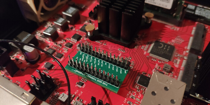
Luckily I have managed to find a solution to this! I found a connector series (Samtec FLE) which is “compatible” with the connector on the Ten64 board, which is usually meant only for IDC/ribbon cables.
When you only need to access some of the GPIO lines this is definitely more convenient. BUT this is a bit of a hack so it’s not suited to serious production applications. You have to be very careful that you align the connector perfectly, as the plugin board connector doesn’t have the mechanical key and shoruding that the mainboard has.
We are considering changing the GPIO header type and/or adding separate breakouts for certain lines (e.g I2C) in future Ten64 revisions.
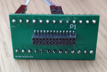
GPIO breakout
This little board splits the 26-pin connector into two rows of “standard” 2.54mm/0.1" pitch pins.
mikroBUS adapter
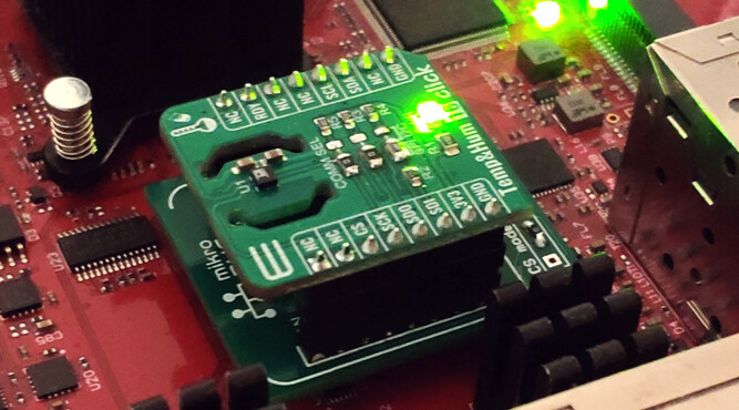
This allows certain mikroBUS “click” boards to be used with the Ten64 (generally those using I2C, UART and GPIOs only, and SPI via bitbang in some cases).
How do I get one of these?
These are not Traverse products. I designed these in my own time. All faults with them are mine
Unless you are in Australia it’s not worth trying to sell/send one to you, but these boards are relatively easy to assemble. So I have shared them on PCBWay. You can add it into your cart and they will fabricate the PCBs for you on demand:
The Altium design files and more information can be found here:
Software support
The current Ten64 firmware doesn’t support device tree overlays, meaning you will need to edit and reflash the system device tree to describe any hardware you plug in (especially for I2C and SPI). This is definitely something that will be added in the “1.0” firmware.
Happy Hacking!
(And be careful, the GPIOs are connected directly to the LS1088 and may not be forgiving as many microcontroller boards to accidents)